RealSense D435i Accuracy (Indoors)
This article is about the accuracy of the RealSense D435i depth camera capturing frames 640 x 480 frames at 30 fps indoors.
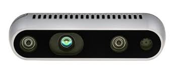
Research into stereo 3D reconstruction can be frustrating because it is hard to find good quality streaming stereo cameras. For me, the Intel RealSense camera range has been a much needed solution to this problem, and so I am a little sad that Intel is shutdown down its RealSense division [Link]. However fortunately for now, they are still selling the D435i camera range. This article is about using the “out the box” functionality of the D435i to make 3D reconstructions of small objects within indoor environments.
What is the Intel RealSense D435i Camera?
The Intel RealSense D435i is a depth camera that is capable of simultaneously acquiring a color image, a depth map and camera motion information (gyroscope and accelerometer) as a simultaneous capture. The key advantage of this camera is that for quick and dirty research, you get depth and camera pose information “out the box” which is very useful. As a vehicle for a complete solution for a fully fledged system, I am not a fan of the color camera so I tend to turn it off (and substitute with a separate better color camera), and the pose estimation is something I will examine in another article.
The real feature of this camera depth map acquisition. This depth acquisition is achieved either by stereo matching using a high speed semi-global approach [Link], or by a structured light approach (depending on whether the structured lighting projector is switched on and whether the patterns are drowned out by sunlight or not). Actual acquisition is achieved through two IR sensors with a baseline of approximately 50mm.
| Attribute | Description |
|---|---|
| Camera Type | Infra-red camera |
| Image Size | $1280 \times 720$ pixels (maximum) |
| Frame Rate | $30$ fps |
| FOV | $87^{\circ} \times 58^{\circ}$ |
| Base Line | $50$ mm |
| Ideal Range | $0.3$ m - $3$ m |
| Shutter Type | Global Shutter |
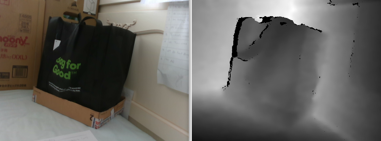 An example of a color image and associated depth map captured and aligned by the RealSense D435i Camera.
Research Question
A key advantage of using the RealSense D435i Camera (RealSense) is that it produces calibration parameters and depth maps “out the box”. However, before using these elements, it seems like a good idea to analyze the quality of these outputs. This article details an experiment, in which, it was attempted to verify the accuracy of the calibration parameters and the depth map generated by the RealSense, based on the consistency between these two elements. Unfortunately, to due the data heavy loads outputted by the RealSense, our testing hardware was only capable of reliably streaming at a resolution of $640 \times 480$ pixels.
Methodology
Extraction of 3D points via depth map
The RealSense is capable of producing synchronized RGBD measurements (RGB color and Depth) by aligning data captured from its RGB color camera with its generated depth map. This can be achieved using the librealsense2 API as follows:
// Retrieve the frames
auto frameset = _pipeline->wait_for_frames();

// Perform the alignment stuff
auto profile = _pipeline->get_active_profile();
auto colorStream = profile.get_stream(RS2_STREAM_COLOR).stream_type();
auto aligner = rs2::align(colorStream);

// retrieve the current depth scale
auto depthScale = GetDepthScale(profile.get_device());

// Get alignment processor
auto processed = aligner.process(frameset);

// Trying to get both other and aligned depth frames
auto colorFrame = processed.first(colorStream);
auto depthFrame = processed.get_depth_frame();
The same API can then also be used to extract the calibration parameters from the camera as follows:
/**
 * @brief Retrieve calibration parameters
 * @return The calibration parameters
 */
Calibration * RealCamera::GetCalibration()
{
    auto profile = _pipeline->get_active_profile();
    auto colorStream = profile.get_stream(RS2_STREAM_COLOR).as<rs2::video_stream_profile>();
    auto intrinsics = colorStream.get_intrinsics();

    Mat camera = (Mat_<double>(3,3) << intrinsics.fx, 0, intrinsics.ppx, 0, intrinsics.fy, intrinsics.ppy, 0, 0, 1);
    Mat distortion = (Mat_<double>(5, 1) << intrinsics.coeffs[0], intrinsics.coeffs[1], intrinsics.coeffs[2], intrinsics.coeffs[3], intrinsics.coeffs[4]);

    return new Calibration(camera, distortion);
}
The distortion parameters of the camera relate to the Brown-Conrady model [Link]. Using this model, it is possible to remove distortion using the OpenCV API’s [Link] undistort function [Link].
Once distortion has been removed, we can then map 2D image coordinates into 3D space with respect to the camera coordinate system as follows:
Given depth map $Z = D(u,v)$ where $Z$ is the depth measured at pixel $[u,v]^{\top}$. Given calibration focal parameters $f_x$ and $f_y$, along with the optical center $[c_x, c_y]$, it is possible to (using the pinhole model [Link]) map 2D coordinates to 3D as:
$X = \frac{Z(u - c_x)}{f_x}$
$Y = \frac{Z(v - c_y)}{f_y}$
$Z = Z$
Detecting 3D grid coordinates using ChArUco
OpenCV provides a useful calibration and tracking grid called a ChArUco board [Link].
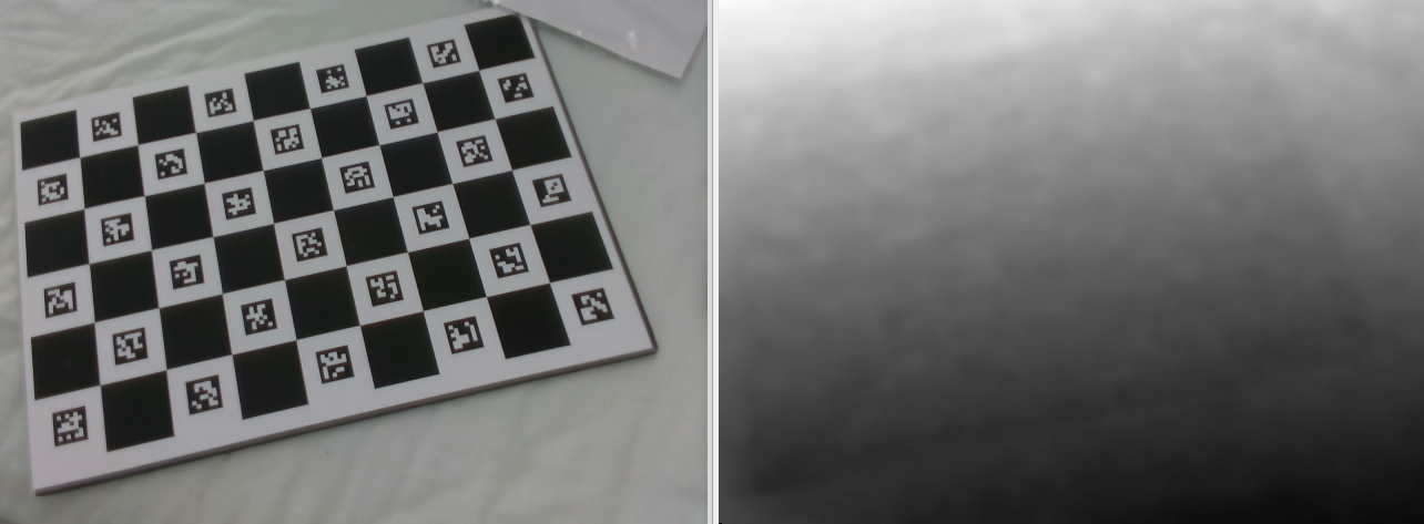 An image of the Charuco board (along with a corresponding depth map) as captured by the RealSense.
A ChArUco board makes it easy to accurately determine the 2D image locations of markers on the board (called ArUco markers), leading to easy detection of the grid corners:
// Create variables
vector<int> ids; vector<PointSet> points, rejected; vector<int> gridCornerIds; vector<Point2f> gridCorners;

// Detect the ArUco markers on the board
aruco::detectMarkers(image, board->dictionary, points, ids);

// Handle the case that no ArUco markers were visible
if (points.size() < 1) throw runtime_error("Unable to detect any ArUco markers on the board!");

// Find the Grid markers
aruco::refineDetectedMarkers(image, board, points, ids, rejected);

// Handle the case that no corners were found
if (points.size() < 1) throw runtime_error("Unable to detect grid points");

// Refine the grid points to get subpixel accuracy
aruco::interpolateCornersCharuco(points, ids, image, board, gridCorners, gridCornerIds);
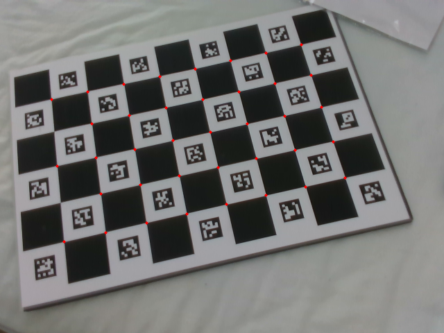 A ChArUco board with its detected corners marked in red.
Once corners have been detected, it is then possible to use OpenCV to detect the pose of the ChArUco board, given the calibration parameters.
Log() << "Calculating Pose" << LoggerBase::End();
Vec3d rvec, tvec;
solvePnPRansac(_scenePoints, _objectPoints, _camera, _distortion, rvec, tvec, false, 9000, 3, 0.99, noArray(), SOLVEPNP_ITERATIVE);
The function solvePnPRansac estimates a $4 \times 4$ pose matrix $P$ (with 6 degrees of freedom: 3 for rotation and 3 for position) using gradient descent [link], and includes Random Sample Consensus (Ransac) [link] noise filtering.
As an input to pose estimation, one needs to specify a 3D coordinate for each corner of the ChArUco grid. These corners are typically specified in the coordinate system of the ChArUco grid, and so, the form of the $i$th corner coordinate will be $g_i = [\alpha_i b, \beta_i b, 0]^{\top}$, where $b$ is the length of a square cell in the grid, and $\alpha_i$ along with $\beta_i$ specify the location. The pose $P$ transforms the 3D grid point $g_i$ to the corresponding point in camera space $c_i$ as follows:
$c_i = P g_i$
Reconciling Approaches
Given the two derivations of the 3D locations of the ChArUco corner points above, we can find corner points by
- Calculating the 3D location of the detected ChArUco corners using the depth map and the pinhole model.
- Calculating points using the specified ChArUco corners along with the pose transform $P$. It is assumed that if the depth map and calibration parameters are sound, then these two different approaches should lead to similar results.
Evaluation of Results
Difference in 3D locations
Given the 3D location of the ChArUco corner $c_i$ as estimated using pose $P$ and the corresponding location of the ChArUco corner $c_i’$ as estimated using the depth map, the obvious choice of metric is to find the Eucidean distance between the two:
$\epsilon_i = \sqrt{(X_i - X_i’)^2 + (Y_i - Y_i’)^2 (Z_i - Z_i’)^2}$
given that $c_i = [X_i, Y_i, Z_i]^{\top}$ and $c_i’ = [X_i’, Y_i’, Z_i’]^{\top}$
Which is typically written in short hand as:
$\epsilon_i = || c_i - c_i’ ||$
It was also considered useful to look at the error in depth $Z$, which is considered to be the largest contributor to overall error. Depth error was found as follows:
$\epsilon_{i: \delta} = | Z_i - Z_i’ |$
Pixel Error
The problem with determining error in 3D space is that “pin-hole” cameras are best modelled using perspective projection [Link]. This means that the resolution of elements further away is different (smaller) to the resolution of elements close by (larger). Thus there is a natural bias towards closer scene elements, leading them to have less error than elements further way.
In order to overcome this, we back-project 3D points onto the image plane 2D and measure the difference in pixels. Pixels have an important property, they are the smallest unit of available within an image. Therefore if our error is less than a pixel, this resembles some sort of optimal result. For this reason, if our findings indicate and error that is “sub-pixel”, this will lead us to conclude that the RealSense “out of the box” parameters are good enough for further research.
Note that back projection is relatively easy, if we assume that the corresponding image point for $c_i = [X_i, Y_i, Z_i]^{\top}$ is $p_i = [u_i, v_i]^{\top}$ then according to the pinhole model:
$u_i = \frac{f_x X_i}{Z_i} + c_x$
$v_i = \frac{f_y Y_i}{Z_i} + c_y$
The same applies to $c_i’$ and $p_i’$. The error in pixels can then be found as:
$\epsilon_{pixels:i} = || p_i - p_i’ ||$.
Plane Error
Another aspect of interest was the visible variance of depth measurements in the depth map. In these indoor experiments, it is possible to mitigate some of this by turning on the structured lighting, which projects infra-red texture into the scene (which helps with stereo matching). However there still were some fluctuations visible, even in the structured lighting enhanced depth maps. Note that the visual magnitude of these fluctuations could have been exaggerated somewhat by an increase in contrast that was applied to the depth map in order to improve the visibility of the individual elements.
Our implementation of this measure was to first performed a plane fitting of the 3D corner points $c_i$. This was achieved by solving for plane coefficients $a$, $b$, $c$, $d$ given the plane equation $aX + bY + cZ + d = 0$. Next the average deviation of points was determined to represent the fluctuation from the plane. Deviation was determined using the deviation equation:
$\epsilon_{plane} = \frac{| aX + bY + cZ + d |}{\sqrt{a^2 + b^2 + c^2}}$
Experimental Description and Results
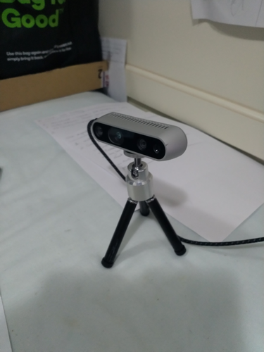
The RealSense camera on the stand used to acquire images.
The RealSense was positioned at a fixed location within the scene. A calibration board was placed in front of the camera and moved back iteratively while 5 images were captured. It was found that after a distance of 1151 meters the system was unable to detect the corners of the ChArUco markers (the resolution across the ArUCo markers DICT_6X6_250 was too low to detect them).
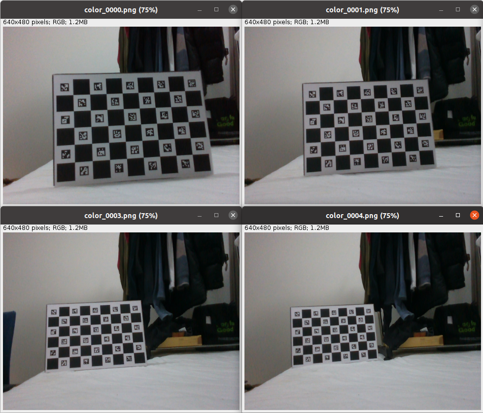 A sampling of the ChArUco board images as they are moved further way from the camera.
| Parameter | Value |
|---|---|
| Grid Size | $4 \times 7$ blocks |
| Block Size | $45.375$ millimeters |
The size of the grid used was $4 \times 7$ square blocks with a side length of $45.375$ mm. The calibration object was made from cardboard stuck (with double sided tape) to a matte laminated printed marker.
| Parameter | Value |
|---|---|
| $f_x$ | 611 |
| $f_y$ | 611 |
| $c_x$ | 327 pixels |
| $c_y$ | 251 pixels |
Intrinsic parameters returned by the RealSense for the setting $640 \times 480$.
The calibration parameters produced by the RealSense are shown in the table above. The distortion coefficients were all zeros, indicating that distortion had been removed by the system.
| No | Depth | 3D Error | Z Error | Plane Error | Pixel Error |
|---|---|---|---|---|---|
| 1 | 621 | 1.06 | 0.96 | 0.91 | 0.27 |
| 2 | 745 | 1.59 | 1.54 | 1.29 | 0.15 |
| 3 | 848 | 4.01 | 3.90 | 2.33 | 0.24 |
| 4 | 995 | 10.50 | 10.23 | 2.90 | 0.39 |
| 5 | 1151 | 12.42 | 12.05 | 3.06 | 0.55 |
Measurement of distance from the target (in millimeters), error in 3D space (in millimeters), error in 3D space only considering the Z -axis (in millimeters), std deviation from the fitted plane (in millimeters) and pixel error of reprojected points (in pixels)
Recorded errors are in the table above. As expected the 3D error and depth error increase significantly with respect to distance from the target. It can also be seen that depth error and 3D error are strongly correlated as expected. Plane error was sub-millimeter at a target distance of 621 mm and increase to 3 mm at a target distance of 1151 mm, indicating that this error is far less significant than the overall error introduced by the change in distance of the camera from the target. However, it is likely that the error is small due to smoothing operations in the depth map post-production by the RealSense API. The most significant observation is that the pixel error is sub-pixel in all cases.
Conclusion
In this article we set out to determine whether the “out the box” measurements (in depth and calibration) from the RealSense camera are usable for basic 3D reconstruction experiments. We designed an experiment in which we reconciled calibration pose estimates of a ChArUco board with corresponding corner points extracted from the RealSense depth map. We also established the benchmark for the experiment: if the difference between the two estimates were sub-pixel (for some part of the measured range), that meant that these values were “workable”, otherwise not. We motivated that this benchmark was independent of distance and that sub-pixel accuracy resembled some sort of optimal result in image based measurements.
After our experiments were concluded, we are satisfied that accuracy is subpixel for the entire tested range (1151 mm) and therefore will move on to the next research problem.